
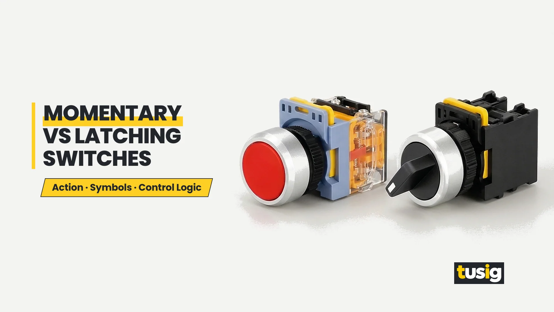
Two commissioning failures show up repeatedly when a new control cabinet reaches the shop floor. In the first failure, an operator presses the start button, the machine runs briefly, and everything stops the instant the finger leaves the cap because a momentary button was fitted where the buyer expected the switch to hold a state by itself. In the second failure, a machine refuses to reset a fault or stop jogging because a latching button was installed where the control circuit needed a spring-return input.
Both problems happen when a panel schedule mixes up contact arrangement and operating action. Choosing a momentary vs latching push button has nothing to do with whether the rear block carries normally open or normally closed contacts. Operating action is a property of the operator head—what the actuator does after the finger lets go—separate from contacts, cap colour, and illumination. Just as important, when a panel position needs a maintained result, there are three different ways to achieve it, and only one of them is a latching push button.
What a Momentary Push Button Does
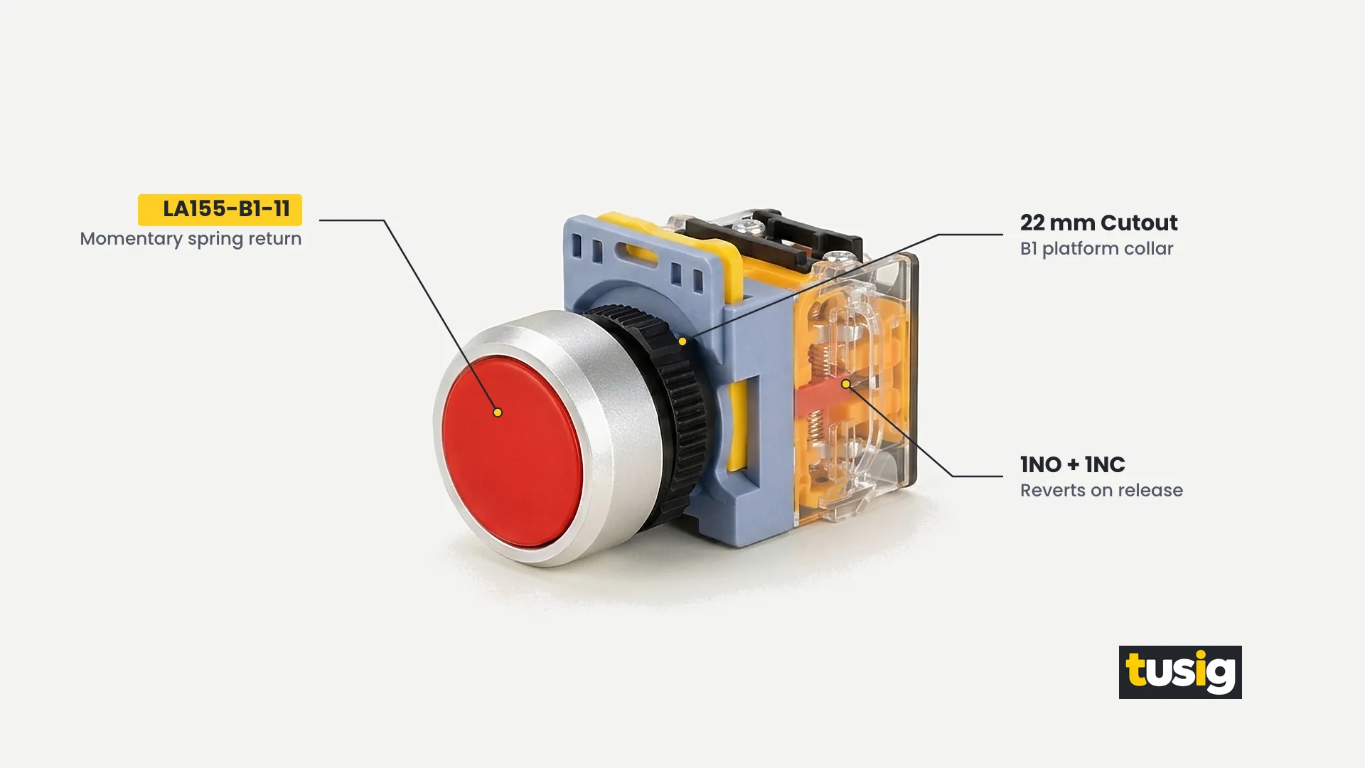
A momentary push button switch changes the state of its electrical contacts only while a finger or palm holds the operator down. Inside the actuator head, a return spring opposes the plunger travel so that the instant external pressure is removed, the cap returns to its unpressed home position and the contacts revert to their normal at-rest state. Because the operator stores no mechanical state after release, every press delivers a temporary input whose length matches the operator’s touch.
The table below shows how the two contact types inside a momentary operator behave across a complete press-and-release cycle.
| Operator State | NO Contact | NC Contact |
|---|---|---|
| At rest | Open; circuit path is interrupted while the button sits unpressed | Closed; circuit path conducts continuously while the button sits unpressed |
| Pressed | Closed; circuit path conducts only while finger pressure holds the cap down | Open; circuit path is interrupted only while finger pressure holds the cap down |
| Released | Open; internal return spring restores the actuator and re-opens the contact path | Closed; internal return spring restores the actuator and re-closes the contact path |
Choose a momentary operator whenever a panel position must deliver a temporary command pulse that ends immediately on release rather than storing a mechanical on or off position inside the button head.
In industrial control panels, momentary push buttons handle most routine operator inputs. Typical tasks include start and stop inputs to a control system, jog and inching commands where a mechanism must move only while the operator’s finger holds the cap, fault reset pulses, and alarm acknowledgement inputs. In each of those tasks, a contact that stayed transferred after release would either hold an axis in motion unintentionally or block a subsequent stop or reset input.
Across Tusig Electric’s 22 mm plastic push buttons range, where a product page states an action for its push button and mushroom models, it states Momentary—including the flush LA155-A1-11, extended LA155-A1-11H, flush LA155-B1-11, illuminated flush LA155-B1-11D, mushroom LA155-B1-11M, and flush LA155-P2-BA31—while the double push button SA155-B8-11R is stated as Spring return.
What a Latching Push Button Does
A latching push button switch sets and mechanically holds its contact state on the first press, then returns to its original state on a second press (or a release action, by mechanism type). When the operator presses and lifts a finger off the cap, an internal catch or detent keeps the plunger and contact carrier in the actuated position. Evaluating a momentary vs latching push button starts with recognising that this mechanical catch replaces finger pressure until someone actuates the switch again.
The table below uses the same three-row format as the momentary section so the two actions can be compared row by row.
| Operator State | NO Contact | NC Contact |
|---|---|---|
| At rest | Open; circuit path is interrupted while the latching mechanism sits released | Closed; circuit path conducts continuously while the latching mechanism sits released |
| Pressed | Closed; first press transfers the contact and the internal catch holds it closed after release | Open; first press opens the contact and the internal catch holds it open after release |
| Released | Open; second press or release action frees the catch and re-opens the contact path | Closed; second press or release action frees the catch and re-closes the contact path |
Specify a latching push button device type only when the panel position itself must mechanically retain an on or off contact state with no control logic behind it.
As a general device type in the market, a latching push button is used where a panel position must hold an on/off state by itself without a relay coil, contactor hold-in path, or controller logic behind the door—such as switching a local cabinet light or a standalone auxiliary load. Because the state is stored by a mechanical detent inside the switch rather than by an energised circuit, its response to power loss differs fundamentally from a circuit-held state.
If electrical supply to the panel is lost while a latching push button is latched, the mechanical state stays where it was left. Unlike a circuit-held state that drops out when control power disappears, a mechanically latched button keeps its contact path transferred during the outage and conducts immediately when power returns.
Momentary vs Latching at a Glance
Comparing a momentary vs latching push button side by side shows why two operators that fit the same 22 mm panel cutout and carry the same contact arrangement behave differently in service. Both actions can operate 1NO + 1NC, 1NO, or 2NO contacts, yet they differ on release, after power loss, and in how the operator knows the active state.
| Specification Criterion | Momentary Push Button | Latching Push Button |
|---|---|---|
| What happens on release | Internal spring returns the actuator and contacts to their at-rest state immediately when the finger lets go | Internal mechanical catch holds the actuator and contacts in the transferred state until a second press or release action |
| State after power loss and restoration | Actuator is already at rest; any circuit-held machine state drops out on power loss and stays off when power returns | Mechanical state stays where it was left during power loss and immediately conducts again when power is restored |
| How the state is known to the operator | Known by the controlled machine’s response or by an indicator lamp, because the button cap returns to the same rest height | Known by button feel or depressed cap position, supplemented where needed by an indicator lamp |
| Typical panel tasks | Start and stop inputs to a control system, jog/inch movement, fault reset, and alarm acknowledgement | Panel positions that must hold an on/off state by themselves with no control logic behind the panel |
| What must be specified | Momentary (spring-return) action, operator form, contact arrangement, and lamp supply plus lens colour if illuminated | Mechanical latching behaviour, release method, contact arrangement, and confirmation that retained state across power loss is intended |
Select the operating action according to how the panel position must behave on release and on power loss, never by contact count alone.
The most common specification error when choosing a momentary vs latching push button is ordering by the word a supplier uses rather than by the behaviour the position needs. In the market, terms such as “maintained”, “alternate”, and “push-on/push-off” are used loosely across push-push buttons, twist-release operators, and rotary selectors. Specify the exact behaviour required on press, on release, and on power loss, then confirm the action against the complete model code before ordering.
Symbols: Reading the Action in a Circuit Diagram
In an electrical circuit diagram, the contact symbols for normally open (NO) and normally closed (NC) paths are the same for both operating actions. Whether an operator is momentary or latching, an NO contact is drawn as an open switch blade at rest and an NC contact is drawn as a closed switch blade at rest. Looking only at the contact symbol will never tell you whether the panel device is a momentary vs latching push button.
The difference is drawn at the actuator symbol attached to the contact linkage. A momentary push button is drawn with a push-button actuator and a spring-return indication showing that the mechanism restores the contact when released. A latching device is drawn with a latching or detent indication—such as a mechanical notch or catch mark along the linkage—showing that the state is held mechanically after actuation.
Use one practical reading rule when checking a drawing: if the diagram’s actuator shows a return spring, the contact state shown on the sheet is the at-rest state only while the button is unpressed; if the actuator shows a latch or detent, the drawn state persists after the operator’s hand leaves the cap. Pair that diagram check with the 22mm push button switch guide so both contact arrangement and operating action are recorded on the panel schedule.
This matters directly during maintenance. Replacing a damaged operator with the other action type changes machine behaviour even when the contact arrangement (NO/NC) is identical. Fitting a latched switch into a spring-return jog position locks the motion command on after one press, whereas fitting a momentary switch into a mechanically held position drops the state out the moment the finger lets go.
Three Ways to Get a Maintained Result
When a control panel position needs to keep a state active after the operator touches it, buyers often ask for a latching push button first. In practice, a maintained result can be achieved three different ways, and only one of them uses a latching push button.
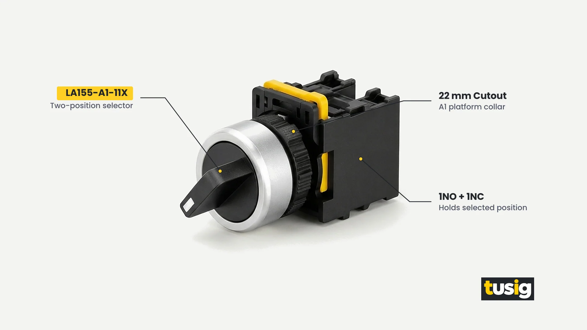
First, a panel can use a maintained operator—a selector switch that holds its selected position by function. Unlike a push button cap whose depth change is small, a selector handle shows its position clearly on the panel face. In the Tusig Electric 22 mm range, two-position and three-position selector switches hold their selected position: verified examples are the two-position LA155-A1-11X, the three-position illuminated LA155-A1-20XSD, the two-position LA155-P2-BD21, and the three-position long-handle LA155-P2-BJ33, plus the key-operated LA155-A1-11Y as the access-controlled variant. For panels specifying metal housings outside the plastic families, see Tusig Electric’s metal push button switches category.
Second, a panel can use momentary buttons plus a holding (seal-in) circuit in the control logic. In the classic start/stop pair, pressing the momentary start button triggers the circuit to hold itself energized after the button springs back open, while pressing the momentary stop button interrupts that hold path. Crucially, a power loss also drops the holding circuit out automatically, which is often the desired behaviour for driven machinery.
Third, a panel position can use a latching push button as a general market device type, where an internal catch inside the button holds the contact state mechanically without control logic.
Follow a clear rule of choice: if the state must survive with no control power or no logic behind the panel, the operator itself must hold it; if a controlled machine must stop on power loss, the state must be held by the circuit behind a momentary button, not by the button.
The Emergency Stop Is Its Own Case
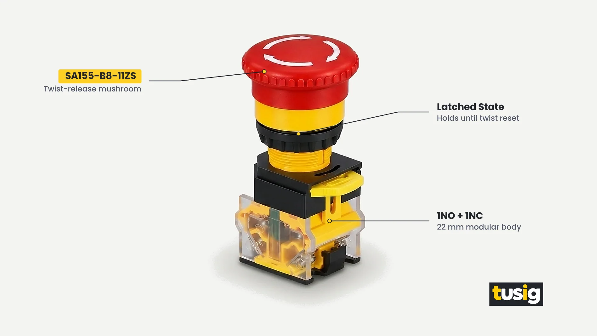
In any momentary vs latching push button discussion, the emergency stop operator is its own case. An emergency stop is neither a momentary button nor a convenience latching button: it latches mechanically on pressing by design and stays latched until deliberately released by its reset arrangement.
That deliberate reset action prevents the stop command from clearing when the palm leaves the head or from toggling back on with a casual tap. In the verified Tusig Electric 22 mm range, emergency stop operators include the twist-release mushroom form SA155-B8-11ZS (which latches mechanically when pressed and is released by its twist-release reset arrangement), plus the non-illuminated emergency stop LA155-B1-11ZS and the illuminated emergency stop LA155-A1-11ZSD.
Always specify the reset arrangement as its own field when ordering an emergency stop operator, alongside the complete model code, contact arrangement, and lamp supply on illuminated forms.
Specification Mistakes That Change Machine Behaviour
Five recurring specification mistakes around momentary vs latching push button selection change how a machine behaves in the field. Each one is prevented by stating a specific field on the panel schedule.
Fitting a latching button where a jog or reset input was needed. Jogging an axis or resetting a fault requires an input that ends the instant the finger leaves the cap. Installing a latching button locks the jog or reset signal active after the first press. Stating Momentary in the operating-action field for every jog, inch, and reset position prevents this fault.
Expecting a momentary button to hold a machine on by itself and reporting it as faulty. Wiring a momentary button such as LA155-B1-11 into a circuit with no holding path causes the machine to stop as soon as the finger lets go, leading installers to report a good switch as defective. Specifying whether state retention belongs to the control circuit or to a maintained selector operator prevents this error.
Swapping to the other action type during maintenance with the same NO/NC arrangement. Because 1NO + 1NC is the standard contact arrangement across many 22 mm operators, swapping a unit by contact count alone can replace a spring-return input with a mechanically held switch or vice versa. Requiring technicians to match both the complete model code and the operating-action field before replacing a switch prevents this mismatch.
Assuming the illuminated version of a model changes its action. Adding an internal indicator lamp does not turn a momentary button into a push-on/push-off switch: both LA155-B1-11 and the illuminated LA155-B1-11D carry a stated Momentary action. Recording operating action and lamp supply as separate schedule fields keeps both independent.
Specifying “maintained” by word alone without stating the required behaviour and release method. Writing only “maintained” on a requisition leaves it unclear whether the position requires a two-position selector, a three-position selector, a key selector, or a twist-release emergency stop. Stating the operator form, actuated behaviour, and release method removes ambiguity before ordering.
How Action Is Specified at Tusig
In the Tusig Electric 22 mm range, operating action is stated by operator family and complete model code. Where a Tusig product page states an action for its push button and mushroom models—including LA155-A1-11 (flush), LA155-A1-11H (extended), LA155-B1-11 (flush), LA155-B1-11D (illuminated flush), LA155-B1-11M (mushroom), LA155-P2-BA31 (flush), and the LA155-P2-BC21 mushroom model with its 40 mm head diameter—it states Momentary, while the SA155-B8-11R double push button is stated as Spring return.
Stated plainly for anyone specifying a momentary vs latching push button: in the Tusig range the push button models carry a stated Momentary action, maintained behaviour is provided by selector operators holding their position, and the action of any complete model must be confirmed against its complete model code before ordering. Two-position and three-position selector switches—LA155-A1-11X, LA155-A1-20XSD (2NO), LA155-P2-BD21 (1NO), LA155-P2-BJ33 (2NO, long handle), and the key-operated LA155-A1-11Y—hold their selected position by function, while emergency stop operators (SA155-B8-11ZS twist-release, LA155-B1-11ZS, and LA155-A1-11ZSD) require the reset arrangement as its own field.
Remember that heads, operators, and contact blocks do not interchange across the LA155 A, B, P2, and SA155 platforms, even though all of them fit a 22 mm cutout. If a panel schedule needs a behaviour that the stated data does not cover, ask with your inquiry instead of assuming. See the 22mm push button switch selection guide for the full four-field specification method.
Conclusion
Resolving the momentary vs latching push button choice comes down to specifying behaviour before hardware. Choose the operating action by the behaviour the panel position must produce, read that action in the circuit diagram by the actuator symbol rather than the NO or NC contact blades alone, and remember that a maintained result can come from the operator or from the circuit. Because operator-held states persist through power loss while circuit-held states drop out, they fail differently and are not interchangeable choices. Send your panel schedule with the required operating action, contact arrangement, and complete model code stated per position to Tusig Electric for a specification check.