
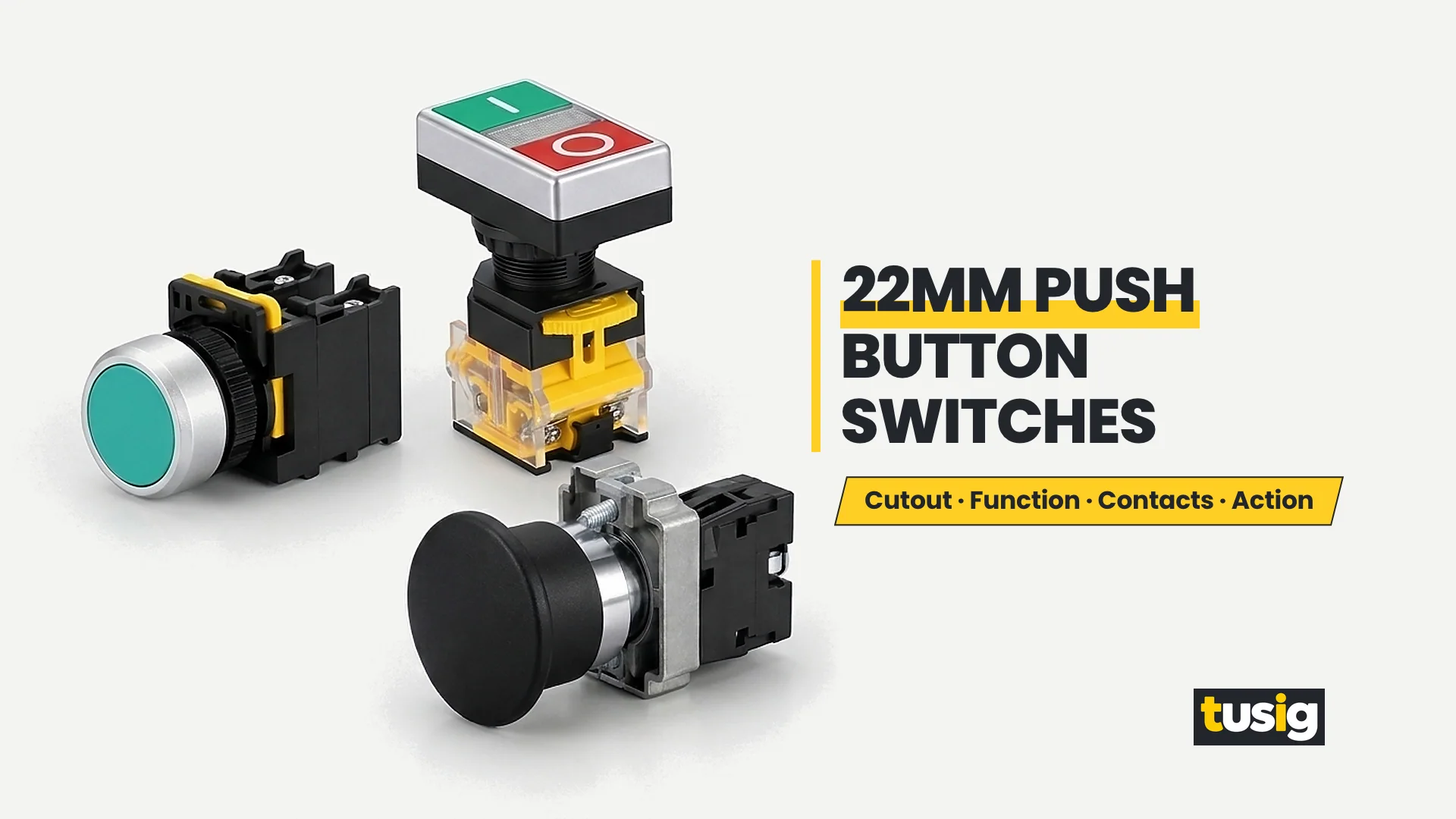
Looking at the front door of a machine control cabinet, five or six round operators in a row can look almost identical. When a panel builder or OEM engineer searches for a 22mm push button switch, the immediate job is to fill those panel positions and write a clean bill of materials. Yet positions that look the same on the front face often require different functions, contact arrangements, and operating actions behind the panel. One position sends a brief start pulse, the next selects an operating mode and holds its position, a third needs an illuminated cap fed by an independent lamp circuit, and a fourth serves as an emergency-stop position with a specific reset arrangement.
Purchasing mistakes happen when all of those requirements are compressed into a vague note such as “22 mm red button” or a partial prefix. A complete specification states four separate fields for every position: the panel cutout size, the operator function, the contact arrangement, and the operating action—plus lamp supply and lens colour on illuminated models. Across the Tusig Electric plastic push buttons range (LA155 A, B, and P2 platforms plus the SA155 modular platform), “one 22 mm system” means coordinated selection in one panel schedule; it never means heads, collars, or contact blocks from different platforms (A, B, P2, SA155) are interchangeable.
22mm Is the Cutout, Not the Head Size
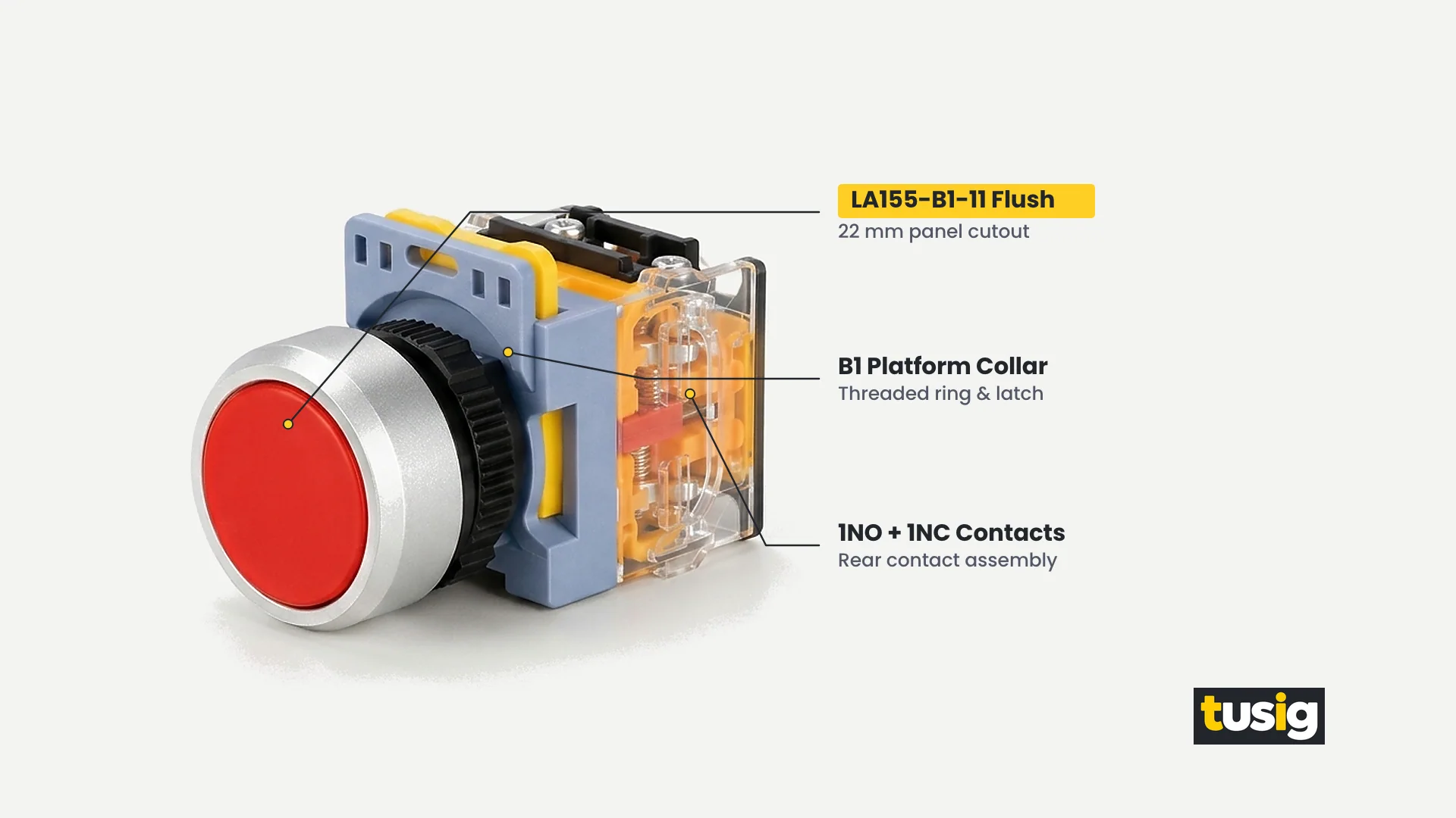
Every model covered in this article mounts through a 22 mm circular opening in the panel door or enclosure cover. That 22 mm figure is the mounting cutout for the threaded neck and collar that pass through the sheet metal, not the outer diameter of the button head in front of the panel. The visible bezel or cap in front of the panel is always larger than the 22 mm hole so that the front flange seats firmly against the panel surface.
On mushroom operators, the difference between the mounting hole and the actuator head is even larger. In the verified Tusig range, the LA155-P2-BC21 mushroom push button fits a 22 mm panel cutout while carrying a 40 mm mushroom head in front of the panel. If a layout drafter treats 22 mm as the outside head width, adjacent mushroom caps, selector levers, or legend plates placed too close together will crowd each other and leave too little room for an operator’s fingers.
When laying out a new panel, check two spatial clearances before approving the door fabrication drawing. First, check the center-to-center head spacing between adjacent positions so wide heads—such as the 40 mm mushroom head on LA155-P2-BC21 or rectangular double push button heads—do not interfere. Second, check the model’s dimension drawing for the assembled device’s rear space behind the panel door so the contact body and wire bends clear internal sub-plates and framing.
For a replacement 22mm push button switch, compare the existing panel opening and available rear space with the proposed assembly’s dimension drawing, and never substitute the front head outer diameter for the cutout diameter. Where an application requires metal switches with other mounting sizes outside this 22 mm plastic platform range, see Tusig Electric’s metal push button switches category.
Start With the Operator Function
Before choosing cap colours or reading contact suffixes, write down in plain words what the operator must do at each panel position. A photograph of a button head on a requisition sheet cannot replace a functional description: a flush cap, an extended cap, a mushroom head, and an emergency-stop head can all sit in a 22 mm hole while serving different operational tasks.
The table below maps the verified operator forms in the Tusig Electric 22 mm range to their typical panel tasks and example complete model codes.
| Operator Form | Typical Panel Task in Plain Words | Example Complete Model Code |
|---|---|---|
| Flush push button | Momentary start, reset, or cycle input where a recessed cap helps prevent accidental brushing | LA155-A1-11, LA155-B1-11, LA155-P2-BA31 |
| Extended (raised) push button | Command or stop input where a projecting cap gives immediate finger contact | LA155-A1-11H |
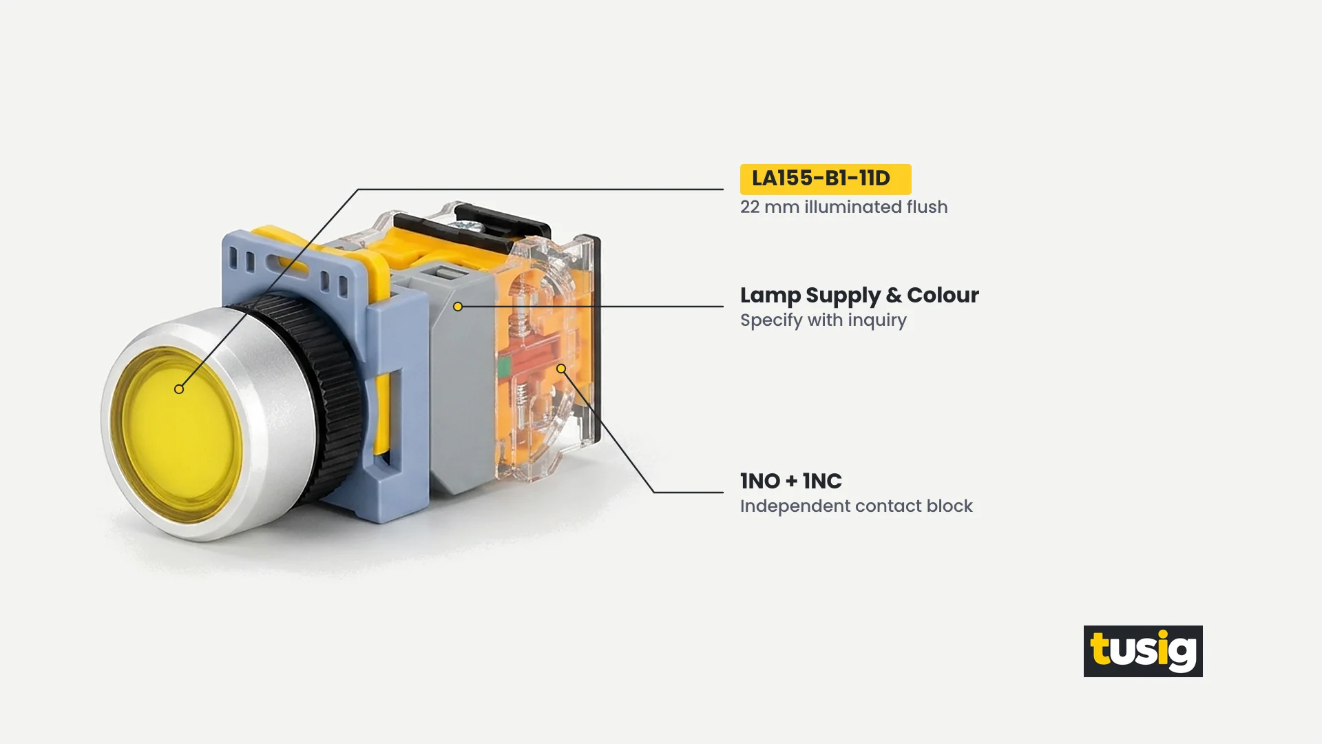
| Illuminated flush push button | Push button command paired with local status indication in one flush lens cap | LA155-A1-11D, LA155-B1-11D, LA155-P2-BW3361, SA155-B8-11D |
| Illuminated extended push button | Raised actuator cap with internal illumination for combined actuation and status feedback | LA155-B1-11HD |
| Mushroom push button | Palm or gloved-hand actuation for stop or manual intervention (40 mm head diameter on LA155-P2-BC21) | LA155-A1-11M, LA155-B1-11M, LA155-P2-BC21 |
| Illuminated mushroom push button | Broad palm actuator combined with internal lens illumination | LA155-B1-11MD |
| Double push button (green I / red O) | Paired start and stop push buttons in a single 22 mm panel cutout | SA155-B8-11R |
| Illuminated double push button | Paired green I and red O buttons with a central indicator window in one 22 mm cutout | LA155-B1-11RD |
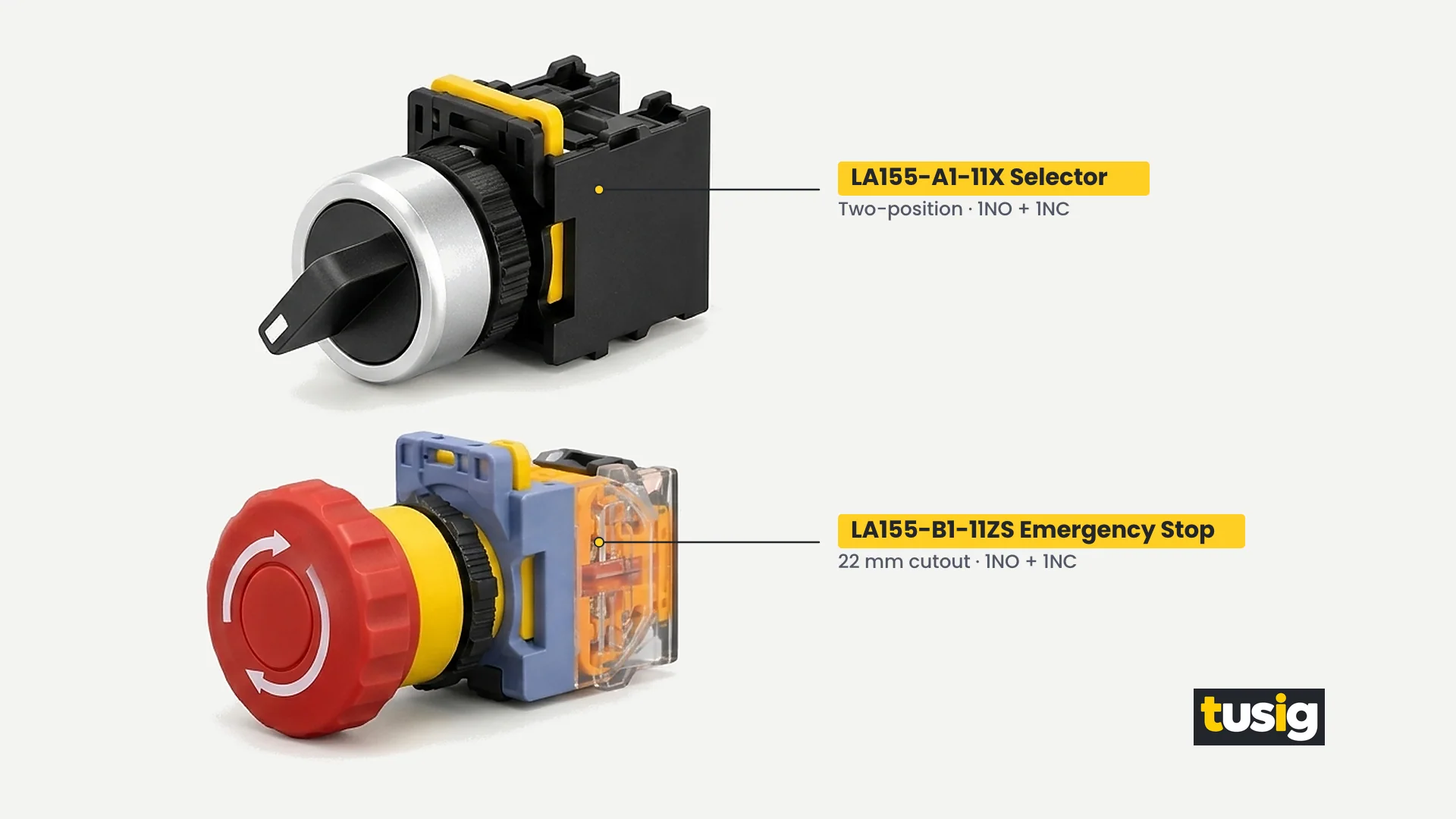
| Two-position selector switch | Rotary two-state selection such as On/Off or Local/Remote | LA155-A1-11X, LA155-B1-11X, LA155-P2-BD21, SA155-B8-11X |
| Illuminated two-position selector switch | Two-position rotary mode selection with an illuminated handle | LA155-B1-11XD |
| Three-position selector switch (short or long handle) | Three-state selection such as Hand/Off/Auto, including the long-handle form on LA155-P2-BJ33 | LA155-P2-BJ33 |
| Illuminated three-position selector switch | Three-position rotary selector with knob illumination | LA155-A1-20XSD |
| Two-position key selector switch | Authorised mode selection or lock controlled by a removable key | LA155-A1-11Y, SA155-B8-11Y |
| Emergency stop operator / twist-release mushroom | Emergency-stop input (non-illuminated LA155-B1-11ZS, illuminated LA155-A1-11ZSD) or twist-release mushroom (SA155-B8-11ZS) | LA155-B1-11ZS, LA155-A1-11ZSD, SA155-B8-11ZS |
| Start-stop push button switch | Self-contained green start and red stop switch with three input and three output terminals | LC3-5 |
Always define the required operator task in words first: select a flush push button (LA155-A1-11, LA155-B1-11, LA155-P2-BA31) for recessed command inputs, an extended (LA155-A1-11H) or mushroom form (LA155-A1-11M, LA155-B1-11M, LA155-P2-BC21) for prominent actuation, and a selector, key, or emergency-stop form when state retention, access control, or reset behaviour is required.
Pay close attention to the difference between the double push buttons (SA155-B8-11R and illuminated LA155-B1-11RD), which pair green I and red O actuators over a 1NO + 1NC contact assembly, and the LC3-5 start-stop push button switch, which is a dedicated green-start / red-stop unit built with three input and three output terminals. When your operators will be housed in local surface enclosures rather than a main cabinet door, review Tusig Electric’s control stations category to coordinate enclosure layouts and hole counts.
Reading the LA155 Model Code
In the LA155 A1 and B1 families and the SA155-B8 series, the letter and number markers at the end of the model code identify the contact arrangement, operator head form, and illumination. The table below lists the verified markers and what still has to be confirmed for the complete model.
| Marker | Meaning | Still to Confirm per Complete Model |
|---|---|---|
| 11 | 1NO + 1NC contact arrangement | The complete offered assembly |
| 20 | 2NO contact arrangement (as in LA155-A1-20XSD) | The complete offered assembly |
| D / HD | Illuminated / illuminated high-head (extended) form | Lamp supply and lens colour |
| ZS / ZSD | Emergency-stop form / illuminated emergency-stop form | Reset arrangement and contacts |
| Y | Key-operated form | Key removal positions and action |
| M / MD | Mushroom / illuminated mushroom form | Intended function and action |
| X / XD | Two-position selector / illuminated two-position selector | Contact sequence and return behaviour |
| XS / XSD | Three-position selector / illuminated three-position selector | Positions, contact sequence and return behaviour |
| H / R | Extended head / double push button | Exact model-specific behaviour |
Use this marker table to read existing catalogue codes, never to invent new combinations. Always copy a complete verified model code exactly—such as LA155-A1-11, LA155-A1-11D, LA155-A1-11H, LA155-A1-11M, LA155-A1-11X, LA155-A1-11Y, LA155-A1-11ZSD, LA155-A1-20XSD, LA155-B1-11, LA155-B1-11D, LA155-B1-11HD, LA155-B1-11M, LA155-B1-11MD, LA155-B1-11X, LA155-B1-11XD, LA155-B1-11ZS, LA155-B1-11RD, LA155-P2-BA31, LA155-P2-BC21, LA155-P2-BD21, LA155-P2-BJ33, LA155-P2-BW3361, SA155-B8-11X, SA155-B8-11D, SA155-B8-11Y, SA155-B8-11R, or SA155-B8-11ZS—and keep the platform designation (A1, B1, P2, or SA155-B8) attached to the code on every schedule row.
Contacts: State the Arrangement Separately
The rear contact assembly determines how the operator switches the connected control circuit. Across the verified Tusig Electric 22 mm range, three contact arrangements exist:
- 1NO + 1NC: The standard arrangement across the LA155-A1 family (LA155-A1-11, LA155-A1-11D, LA155-A1-11H, LA155-A1-11M, LA155-A1-11X, LA155-A1-11Y, LA155-A1-11ZSD), the LA155-B1 family (LA155-B1-11, LA155-B1-11D, LA155-B1-11HD, LA155-B1-11M, LA155-B1-11MD, LA155-B1-11X, LA155-B1-11XD, LA155-B1-11ZS, LA155-B1-11RD), and the SA155-B8 modular operators (SA155-B8-11X, SA155-B8-11D, SA155-B8-11Y, SA155-B8-11R, SA155-B8-11ZS).
- 1NO: The arrangement on the LA155-P2 flush push button (LA155-P2-BA31), 40 mm mushroom push button (LA155-P2-BC21), illuminated push button (LA155-P2-BW3361), and two-position selector switch (LA155-P2-BD21).
- 2NO: The arrangement on the LA155-A1-20XSD three-position illuminated selector switch and the LA155-P2-BJ33 three-position long-handle selector switch.
Conceptually, a normally open (NO) contact stays open at rest and closes the connected circuit path when the operator is actuated, while a normally closed (NC) contact stays closed at rest and opens the circuit path when actuated. A 1NO + 1NC 22mm push button switch provides one of each path in the same rear assembly, whereas 1NO provides a single make path and 2NO provides two independent make paths for multi-position selection.
Always list the contact arrangement in its own schedule column. Never merge a selector switch (such as LA155-A1-11X) and a flush push button (such as LA155-A1-11) into a single schedule row just because both carry the “11” marker for 1NO + 1NC contacts. When matching spare contact blocks, protective covers, or operator heads to an existing platform, consult the push button accessory compatibility guide.
Momentary, Spring Return and Maintained Action
Operating action describes whether an actuator returns to its starting position automatically upon release or stays in its actuated position. Selecting the right action depends on whether the panel position sends a transient pulse or holds a continuous mechanical state.
With momentary (or spring-return) action, pressing the button shifts the contacts only while finger force is held; releasing the cap allows the internal spring to return the actuator and contacts immediately to rest. With maintained (latched) action, the mechanism stays in its actuated state after release until a second action resets it.
Apply the verified Tusig product data strictly when writing your schedule. Where a Tusig product page states an action for the models in this guide, it states Momentary (across most push button and mushroom models) or Spring return (specifically on the SA155-B8-11R double push button). Rotary selector operators (such as LA155-A1-11X, LA155-B1-11X, LA155-P2-BD21, LA155-P2-BJ33, LA155-A1-20XSD, and SA155-B8-11X) hold their selected rotary position by their function. Never assume or state that a named Tusig push button model is a maintained or latching model unless the product data states it. Whenever the operating action of a complete model is not stated in the verified data above, mark the required action on your schedule to be confirmed against the complete model code before ordering.
Illuminated Versions: Lamp Supply Is Its Own Field
An illuminated 22mm push button switch or selector combines command actuation and visual status indication in one 22 mm panel opening. In the verified Tusig range, illuminated forms exist across five operator types:
- Illuminated flush push buttons: LA155-A1-11D, LA155-B1-11D, LA155-P2-BW3361, and SA155-B8-11D
- Illuminated extended push button: LA155-B1-11HD
- Illuminated mushroom push button: LA155-B1-11MD
- Illuminated two- and three-position selectors: LA155-B1-11XD and LA155-A1-20XSD
- Illuminated emergency-stop operator: LA155-A1-11ZSD
On every illuminated model, the internal lamp supply is independent of the circuit switched by the rear contacts. Choosing a code with a D, HD, MD, XD, XSD, or ZSD suffix—or LA155-P2-BW3361—identifies the illuminated operator form and its contact arrangement, but does not state the lamp supply or the lens colour.
In the verified Tusig product data, the rule for illuminated units is to specify the lamp supply and lens colour with your inquiry. Do not assume the contact circuit implies the lamp supply, and never leave lamp details out of the RFQ. Give your panel schedule a dedicated illumination column that records both the required lamp supply and the lens colour for every illuminated position.
Selectors, Key Operators and Emergency Stops in the Same 22mm Panel
Because selectors, key switches, and emergency-stop operators use the same 22 mm panel cutout as standard push buttons, they belong on the same panel schedule—with a few extra fields recorded per position.
- Selector switches: State whether the position requires two positions (LA155-A1-11X, LA155-B1-11X, LA155-B1-11XD, LA155-P2-BD21, SA155-B8-11X) or three positions (LA155-A1-20XSD, LA155-P2-BJ33). Note the handle type where relevant—both short-handle and long-handle forms exist, with a long handle on LA155-P2-BJ33—and record the required contact sequence per position on the schedule so the supplier can confirm return behaviour and contact closure.
- Key-operated switches: Two-position key selector switches exist in the range under LA155-A1-11Y and SA155-B8-11Y (both with 1NO + 1NC contacts). State on the schedule which position or positions require the key to be removable, together with the required action, as an application requirement for the supplier to confirm against the complete model.
- Emergency stop and twist-release mushroom operators: The verified range includes a non-illuminated emergency-stop operator (LA155-B1-11ZS), an illuminated emergency-stop operator (LA155-A1-11ZSD), and a twist-release mushroom form (SA155-B8-11ZS), each carrying 1NO + 1NC contacts. Specify the required reset arrangement as its own schedule field (and lamp supply plus colour on LA155-A1-11ZSD) so the complete offered assembly can be confirmed before ordering.
The Panel Schedule: A Copyable Specification Checklist
A panel schedule prevents ordering errors by giving each 22 mm panel position one row with seven explicit columns: panel position, function in words, complete model code, contact arrangement, operating action, illumination + lamp supply + lens colour, and quantity.
The table below provides two worked rows using verified Tusig models—one for the illuminated flush push button LA155-B1-11D and one for the two-position selector switch LA155-A1-11X—where every datum from the verified product range is marked as stated and every project-dependent input is marked as “buyer to specify.”
| Panel Position | Function in Words | Complete Model Code | Contact Arrangement | Operating Action | Illumination + Lamp Supply + Lens Colour | Quantity |
|---|---|---|---|---|---|---|
| PB-01 (Worked Example 1) | Buyer to specify (e.g., Illuminated flush push button command in 22 mm cutout) | LA155-B1-11D (stated) | 1NO + 1NC (stated) | Momentary (stated) | Illuminated flush (stated); Lamp supply: Buyer to specify; Lens colour: Buyer to specify | Buyer to specify |
| SS-02 (Worked Example 2) | Buyer to specify (e.g., Two-position rotary mode selector in 22 mm cutout) | LA155-A1-11X (stated) | 1NO + 1NC (stated) | Two-position selector (stated); contact sequence & return behaviour: Buyer to specify / confirm per model | Non-illuminated (stated); Lamp supply: Not applicable; Colour: Confirm per model | Buyer to specify |
| POS-XX (Copyable Blank Row) | Buyer to specify function and operator form in words | Copy exact code from verified range (keep A1, B1, P2, SA155-B8, or LC3-5 attached) | State 1NO + 1NC, 1NO, or 2NO (or 3-in / 3-out on LC3-5) | State Momentary, Spring return (SA155-B8-11R), selector positions, or reset arrangement: Buyer to specify / confirm | Non-illuminated, or Illuminated + Lamp supply: Buyer to specify + Lens colour: Buyer to specify | Buyer to specify |
Copy the table structure directly into your inquiry sheet: keep the stated model code and contact arrangement unchanged, and fill in every “buyer to specify” cell for your specific machine panel.
Specification Mistakes That Cause Wrong Deliveries
- Ordering by head appearance or colour alone: Requesting “red and green 22 mm buttons” without stating whether the head is flush (LA155-A1-11, LA155-B1-11), extended (LA155-A1-11H), mushroom (LA155-A1-11M, LA155-B1-11M, LA155-P2-BC21), double (SA155-B8-11R), or emergency-stop (LA155-B1-11ZS) leads to mismatched operators on the panel door. Completing the Function in Words field first prevents appearance-only ordering.
- Treating 22 mm as the head diameter: Measuring across the front bezel or across the 40 mm mushroom head on LA155-P2-BC21 causes buyers to order the wrong cutout size, or causes drafters to space holes too tightly. Recording 22 mm as the panel cutout and checking the model’s dimension drawing for head spacing and rear space prevents layout and replacement errors.
- Copying a partial model code or joining markers into a code that does not exist: Writing “LA155-11D” drops the platform identifier, while splicing suffixes across rows can create a part number that is not offered. Copying only a verified string into the Complete Model Code column prevents invalid part numbers.
- Assuming parts interchange across the A, B, P2 and SA155 platforms: Sharing a 22 mm panel opening does not mean heads, mounting collars, or contact blocks from LA155-A1, LA155-B1, LA155-P2, and SA155-B8 fit one another. As stated in the introduction, “one 22 mm system” means coordinated selection in one panel schedule, never cross-platform part swapping. Keeping the full platform prefix in the Complete Model Code field ensures each position arrives as a matched assembly.
- Forgetting the lamp supply on illuminated models: Listing LA155-A1-11D, LA155-B1-11D, LA155-B1-11HD, LA155-B1-11MD, LA155-B1-11XD, LA155-A1-20XSD, LA155-A1-11ZSD, LA155-P2-BW3361, or SA155-B8-11D without lamp details delays the order because the model code does not fix the lamp supply or colour. The Illumination + Lamp Supply + Lens Colour column prevents this omission.
- Merging different functions into one schedule row because they share a contact marker: Combining LA155-A1-11, LA155-A1-11X, LA155-A1-11Y, and LA155-A1-11ZSD into one line item because all four carry the “11” marker (1NO + 1NC) erases critical differences in operator form, key removal, and reset behaviour. Keeping Function in Words, Contact Arrangement, and Operating Action as separate columns on individual rows prevents merged-line mistakes.
Conclusion
Every reliable 22mm push button switch specification separates four core fields on the panel schedule—the 22 mm cutout, the operator function in words, the contact arrangement (1NO + 1NC, 1NO, or 2NO), and the operating action—and adds lamp supply plus lens colour as the fifth field on every illuminated model. Keeping those fields distinct on a position-by-position schedule ensures that flush buttons, mushrooms, selectors, key switches, start-stop switches, and emergency-stop operators are specified accurately without mixing parts across platforms. Send your completed panel schedule with full model codes and quantities to Tusig Electric for a specification check against your panel requirements.
References
- Tusig Electric, Plastic Push Buttons — Tusig Electric 22 mm push button, selector, key, and emergency-stop catalogue.
- Tusig Electric, LA155-B1-11D Illuminated Flush Push Button — Tusig Electric product information.
- Tusig Electric, Metal Push Button Switches — Tusig Electric metal panel push button switches.
- Tusig Electric, Control Stations — Tusig Electric push button enclosures and assembled control stations.
- Tusig Electric, Push Button Accessory Compatibility: Contact Blocks, Covers and Operators — Tusig Electric platform accessory compatibility guide.