
Applications
Every panel has a job. Start with the control.
An operator input, a visible status or a local control station: begin with the function, then define the component. Explore Tusig Electric selections for machines and electrical panels.
Discuss your applicationControls across working environments.
Industry reference scenes. Define each component around the actual equipment, panel function and operating conditions.

Transport equipment
Start with the equipment panel and its operating environment; review the exact control and indication requirements.
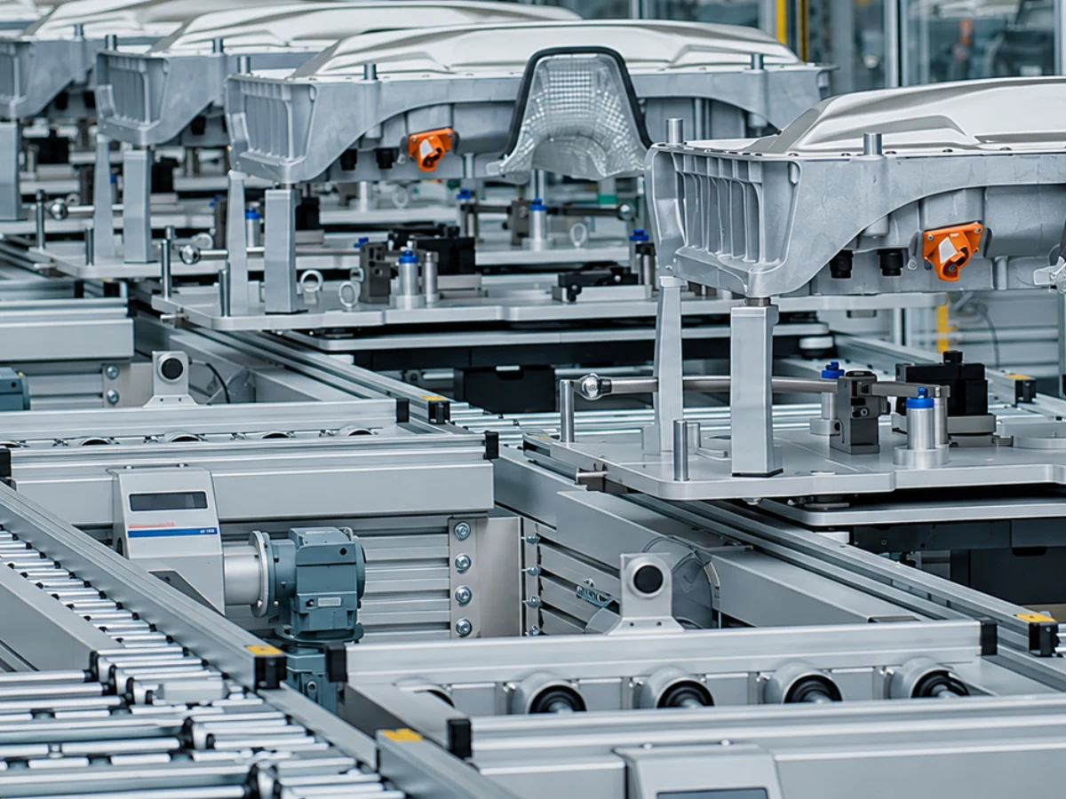
Factory machinery
Define operator commands and visible status for machinery and production equipment.
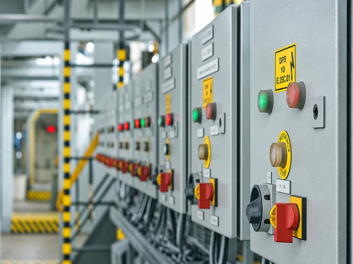
Panel assembly
Match buttons, indicators and accessories to the specified panel schedule.
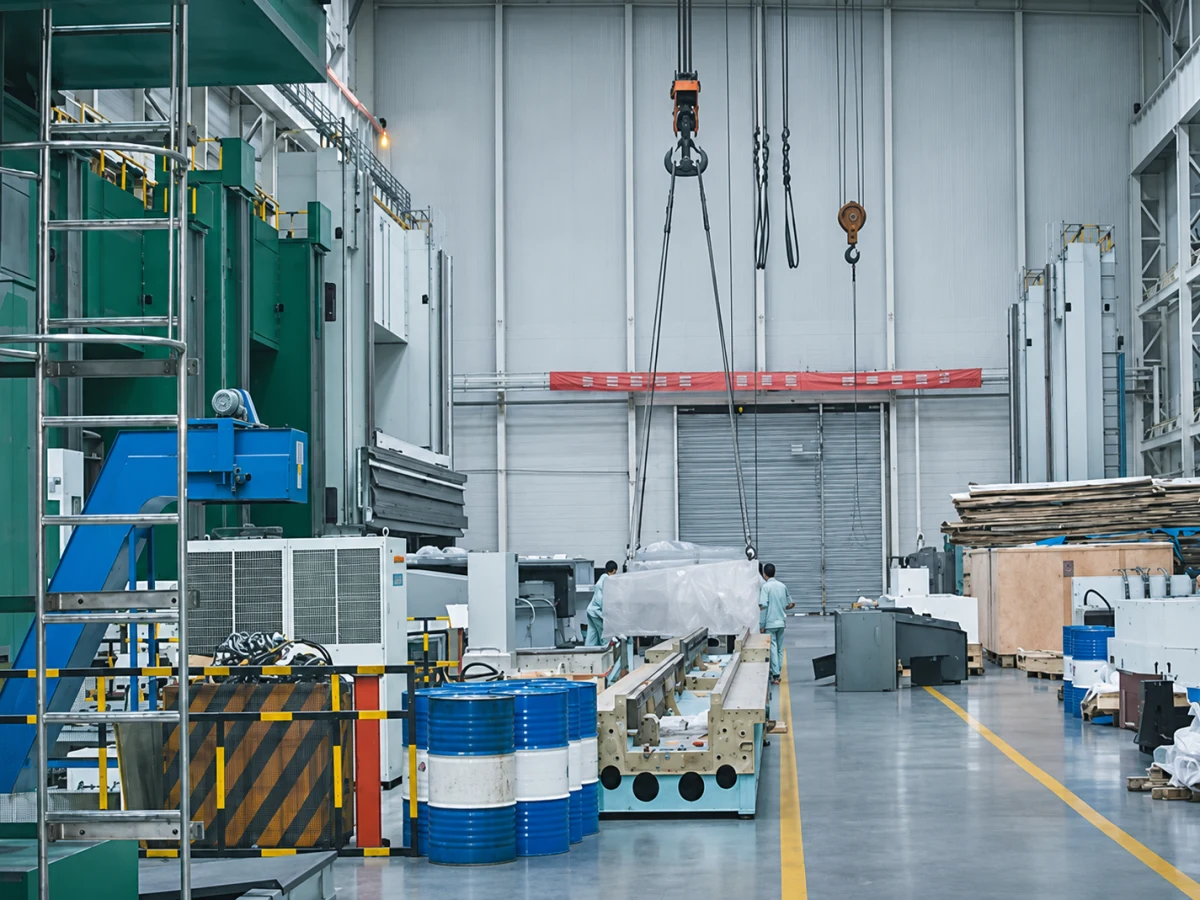
Industrial equipment
Review local control, installation space and signaling requirements for working equipment.
Machinery & equipment
Operator commands that match the machine sequence.
Build a panel schedule for start, stop, mode selection and visible machine status. Select the operating action and contact arrangement for each position before choosing an operator head.
- Operating action
- Momentary or maintained action; selector positions and key-removal requirements.
- Panel fit
- Cutout, panel thickness, space behind the panel and terminal access.
- Circuit
- Control-circuit duty, contact arrangement and lamp supply where needed.
Machine tools
Controls within reach. Status at a glance.
Match the operator layout to the machine function, available mounting space and surrounding conditions. Metal push buttons and joystick switches provide different input forms; select the exact action required by the machine design.
- Operator layout
- Button head form, joystick directions and spring-return or maintained action.
- Installation
- Mounting dimensions, wiring clearance and any required protective cover.
- Environment
- Coolant, dust and cleaning exposure; request the selected model’s applicable protection data.
Power automation
Make the indicated condition easy to identify.
Specify the condition to be shown at each panel position: available supply, running status, a selected mode or another defined signal. Choose the lamp supply and color independently of the signal being monitored.
- Indication task
- What each light means and the required color schedule.
- Supply
- Nominal voltage, AC or DC, and the supply available at the device.
- Connections
- Terminal type, mounting opening and rear-panel clearance.
Control cabinets
One schedule for operators, lamps and accessories.
Bring the panel bill of materials together around complete model codes. Pair each operator with the correct contact arrangement and mounting accessories; for a separate operator station, distinguish an empty enclosure from a configured assembly.
- Panel schedule
- Function, complete model, contact arrangement, lamp configuration and quantity.
- Station layout
- Number of positions, operator arrangement and enclosure dimensions.
- Accessories
- Matching platform and size for contact blocks, covers and other fittings.
Distribution cabinets
Identify panel conditions with a defined lamp schedule.
Choose panel indicators around the intended indication circuit and installation. A pilot light shows the condition assigned to it; the supply rating and wiring arrangement must match the selected model and circuit.
- Signal assignment
- Define the meaning and color of each indicator.
- Electrical match
- Supply voltage, AC/DC requirement and connection arrangement.
- Mechanical match
- Panel cutout, fixing method and available clearance.
Instrument cabinets
Separate status indication from measurement.
Start with the task: a visual status signal, an operator command or a measured value. Use the documented function of the exact model. Keep display requirements separate from the supply voltage of a status indicator.
- Function
- Status indication, operator input or a specified display/measurement task.
- Readability
- Lens color, head form and position on the panel.
- Model evidence
- Request the relevant range, connection and mounting information for the chosen device.
Prepare your inquiry
A useful specification starts with the panel.
Function & circuit
List the operating action, contact arrangement, supply and indication task for each position.
Fit & environment
Include cutout dimensions, mounting space, wiring access and relevant operating conditions.
Models & quantities
Send complete model codes, quantities, a panel schedule and drawings or reference photos where available.
Have a panel schedule or a custom requirement?
Send it to Tusig Electric for model and configuration review.